Policy Key Points
Policy
Table of Contents
Purpose
Scope
Normative References
Types and Classifications of Robots
Robot Programming by Teaching Methods
Robot Working Space
Hazards
Sources of Hazards
Desing Requirements for Robot Components, Systems, and Tools
Risk Assessment Method
Performing the Risk Assessment
Safeguarding Devices Requirements
Robot and Robot Assembly Manufacturing Requirements
Testing and Start-up of Robots and Robot Systems
Robot Assembly Installation
Robot System Troubleshooting, Repair, and Maintenance
Training and Certification of Qualified Associates
Collaborative Robots
Purpose
The purpose of this policy is to provide information and procedures to assure that robots, robot cells, and robot systems are used safety.
Robots are programmable, multifunctional manipulators with moving parts that may cause injuries to Yaskawa associates. As a result, the Occupational Health and Safety Administration (OSHA), the National Institute for Occupational Health and Safety (NIOSH), and the American National Standards Institute (ANSI) recommend the implementation of safety measures to protect robot operators from preventable injuries.
This policy includes safety requirements for the following lifecycle stages:
- Prototyping,
- Manufacturing,
- Product testing,
- Long-term life performance testing,
- Handling and packaging,
- Customer On-Site prove-out visits, and
- Field Service, Decommissioning, and Repair
It also includes safety requirements that are applicable when Yaskawa is the end-user of a robot system or cell, including collaborative robots.
Scope
This policy includes requirements for performing risk assessments and taking necessary actions to reduce the likelihood of severe injuring during each applicable stage of the products lifecycle as they relate to Yaskawa associates and contract workers.
This policy does not address design requirements of the robot, robot cell, or robot system.
For the purposes of this policy, the RIA definition of a robot is used to determine applicability of this policy. The RIA definition of a robot is:
A robot is a reprogrammable, multifunctional manipulator designed to move material, parts, tools, or specialized devices through variable programmed motions for the performance of a variety of tasks.
Use the following decision tree to determine applicability of this policy for an automated machine designed, manufactured, and/or used by Yaskawa:

Normative References
ISO 10218
- Central standard for Industrial Robots
- Consists of two parts:
- ISO 10218-1 describes the safety requirements for the robot manufacturer
- ISO 10218-2 describes the safety requirements for the robot integrator including
-
ANSI/RIA R15.06-2012
- US standard that is the national adoption of ISO 10218-1 and ISO 10218-2
- Provides guidance to Manufacturers, Integrators, and Users
Since ANSI/RIA R15.06 includes all of the requirements of the International Standard (ISO 10218), ANSI/RIA R15.06 will be used as the governing standard for all Yaskawa America, Inc. facilities, regardless of that facilities home nation.
OSHA Directive STD 01-12-002; Guidelines for Robotics Safety
Although the ANSI/RIA R15.06-2012 is a voluntary industry standard, this OSHA directive establishes the ANSI/RIA R15.06-2012 as a compliance standard under the requirements of the OSHA General Duty Clause that requires employers to eliminate known hazards that can cause severe injury or death.
ISO/TS 15066: Robots and Robotic Devices – Collaborative Robots
Applicability of Standards
| Who |
ANSI/RIA R15.06 |
ISO 10218 |
OSHA |
| Manufacturer |
X |
X |
|
| Integrator |
X |
X |
|
| User |
X |
|
X |
Types and Classifications of Robots
Robot Arm Configurations
Industrial robots are available in a wide range of sizes, shapes, and configurations. They are designed and fabricated with different design configurations and a different number of axes or degrees of freedom.
These factors of a robot’s design influence its working envelope (the volume of working or reaching space).
The diagram on the right illustrates the different robot design configurations.
Industrial Robots Major Components
Mechanical Unit: The robot’s manipulative arm and a fabricated structural frame with provisions for supporting mechanical linkage and joints, guides, actuators, control valves, and sensors.
Power Supply: Energy is to various robot actuators and their controllers as pneumatic, hydraulic, or electrical power (or a combination of these sources).
Robot Controller: Performs all required computational functions as well as interface with and control associated sensors, grippers, tooling, and other associated peripheral equipment.
Robot Tooling: Equipment that interacts with parts and components, typically at the end of the robotic arm.
Robot Programming by Teaching Methods
When establishing a robot program, it’s necessary to establish a physical and geometrical relationship between the robot and other equipment or work to be serviced by the robot. To establish these coordinate points precisely within the robot’s working envelope, it’s necessary to control the robot manually and physically teach the coordinate points. To do this as well as determine other functional programming information, three different teaching or programming techniques are used: lead-through, walk-through, and off-line.
Lead-Through Programming or Teaching
This method of teaching uses a proprietary teach pendant (the robot’s control is placed in a “teach” mode), which allows trained personnel physically to lead the robot through the desired sequence of events by activating the appropriate pendant button or switch. Position data and functional information are “taught” to the robot, and a new program is written. When using this technique of teaching or programming, the person performing the teach function can be within the robot’s working envelope, with operational safeguarding devices deactivated or inoperative.
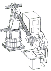
Lead-Through Teaching
Walk-Through Programming or Teaching
A person doing the teaching has physical contact with the robot arm and actually gains control and walks the robot’s arm through the desired positions within the working envelope. During this time, the robot’s controller is scanning and storing coordinate values on a fixed time basis. When the robot is later placed in the automatic mode of operation, these values and other functional information are replayed and the program is run as it was taught.
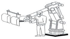
Walk-Through Teaching
Off-Line Programming
The programming establishing the required sequence of functional and required positional steps is written on a remote computer console. Since the console is distant from the robot and its controller, the written program has to be transferred to the robot’s controller and precise positional data established to achieve the actual coordinate information for the robot and other equipment.
Robot Working Space
The three dimensional space that encompasses the movements of all robot through their axes is called the robot working space (previously called the working envelope). Within the working space are three zones:
Maximum Space: The volume of space encompassing the maximum designed movements of all robot parts including the end-effector, workpiece, and attachments.
Restricted Space: The portion of the maximum space to which a robot is restricted by limiting devices. The restricted space limits are defined by the maximum distance that the robot, end-effector, and workpiece can travel.
Operating Space: That portion of the restricted space that is actually used by the robot while performing its task program.

- A fault in the program can cause the robot to extend beyond the operating space into the restricted space.
- A fault in the limiting devices can cause the robot to extend beyond the restricted space into the maximum space.
Hazards
Most robot related injuries do not occur during normal operating conditions. Instead, the occur during any of the following activities when the worker may temporarily be within the robot working space. These activities include:
- Programming,
- Cleaning,
- Adjustments,
- Inspection/Troubleshooting,
- Testing, and
- Repair.
The table below shows the hazards of working within the robot working space:
 Crush between robot and arm fixture
 Crush between arm and non-supporting structure
  Crush between gripper and fixture
  Crush between part and fixture
 Crush between gripper and workpiece
  Impact by robot arm
  Impact by robot wrist
  Impact with gripper
Other hazards that may exist include:
 Caught-in / Caught in-between
  Cranes in robot cell area
  Sources of Energy
  Slips, trips, and falls
 Ergonomic related
  Lifting
  Falling Objects
  Struck-by / Struck-against
 Other not specified
The required risk assessment must address each of these hazards, when present.
Sources of Hazards
The proper selection of an effective robotics safety system must be based on hazard analysis of the operation involving a particular robot or robot system. Among the factors to be considered in such and analysis are the task a robot is programmed to perform, the start-up and the programming procedures, environmental conditions, the location of the robot, requirements for corrective tasks to sustain normal operations, human errors, and possible robot malfunctions. Sources of robot hazards include:
- Human error
- Inherent prior programming, interfacing activated peripheral equipment, or connecting live input-output sensors to the microprocessor or a peripheral can cause dangerous, unpredicted movement or action by the robot from human error,
- The incorrect activation of the teach pendant or control panel is a frequent human error,
- The most frequent human error is over familiarity with the robot’s redundant motions so that an individual places him/herself in a hazardous position while programming the robot, performing maintenance on the robot, or otherwise interacting with the robot.
- Control error
Intrinsic faults within the control system of the robot, errors in software, electromagnetic interference, and radio frequency interference are control errors.
- These errors can occur due to faults in the hydraulic, pneumatic, or electrical sub-controls associated with the robot or robot system,
- Unauthorized access
- Entry into a robot’s safeguarded area is hazardous because the person involved may not be familiar with the safeguards in place or their activation status.
- Mechanical hazards
- Operating programs may not account for cumulative mechanical part failure, and faulty or unexpected operation may occur,
- Lab testing may not consider potential errors in the design process,
- Production testing may not consider defective materials or errors made during assembly,
- Troubleshooting and repair activities may not consider the unknown cause of the failure. When one cause is known, the engineer may not consider other failures that may also exist.
- Environmental hazards
- Electromagnetic or radio-frequency interference (transient signals) should be considered to exert an undesirable influence on robot system operation and increase the potential for injury to any person working in the area,
- Solutions to environmental hazards should be documented prior to equipment start-up,
- Electric, hydraulic, and pneumatic power sources
- Power systems that have malfunctioning control or transmission elements in the robot power system can disrupt electrical signals to the control and/or power-supply lines,
- Fire risks are increased by electrical overloads or by the use of flammable hydraulic oil,
- Electric shock and release of stored energy from accumulating devices can also be hazardous.
- Improper installation
- The design, requirements, and layout of equipment, utilities, and facilities of a robot or robot system, if inadequately done, can lead to inherent hazards,
- This also applies to improper installation in laboratory and production testing work areas.
Considering Failure Modes in Risk Assessment
A common mistake in performing risk assessments is to only consider failure modes that occur when everything is done correctly: there are no defective parts from vendors, there were no defects during assembly, there were no errors in installation. The risk assessment must consider potential defects that occurred previously that could possibly have gone undetected.
Utilization of the Hierarchy of Controls to control hazards
The hierarchy of controls shall be used when determining hazard control methods. Where hazards cannot be eliminated, a combination of controls must be used.
For example, if guards (an engineering control) are used, administrative controls such as warning labels and requiring qualification to enter the area should be used. Hierarchy of Controls
Design Requirements for Robot Components, Robot Systems, and Robot Cells
Robot and Robot System Design Safeguarding Requirements
Requirement Differences between Design for Sale vs. Internal Use Only
All of the requirements in this section apply for robots designed for sale and designed for internal use only, with the following exceptions:
Design Requirements Table
| Specific Requirements for Design for Sale |
Specific Requirements for Internal Use Only |
- Documentation sent to the customer must specify that the customer is responsible for:
- Performing risk assessment for the installation, operation, and maintenance of the robot system,
- Conspicuously identifying the restricted space,
- Providing guarding beyond the restricted space that prevents any body part from entering the restricted space by going around, under, through, or over the guarding,
- Providing emergency stops exterior to the robot cell
- Provisions for lifting must be designed for all discrete elements shipped to the customer that exceed 40 lbs
- Provide training and qualification process for teaching, operating, and maintaining the robot system
- Providing lockout/tagout procedure
- When the E-Stop does not immediately stop all movement, a warning must be included in the technical manual and on a warning label on the robot/robot system. The customer shall include their method of controls to prevent injury in their risk assessment.
- The robot should support the capability, as an option, to include the supplied emergency stop devices in an externally powered circuit so that these devices remain capable of stopping external equipment even with the robot powered off
|
- Installation instructions shall be provided to the installers via written documentation or through direct supervision of a competent member of the design team.
- A pre-installation job safety briefing must be completed with competent representation from the design and installation team.
- The restricted space shall conspicuously be identified.
- Any components used during the assembly of the robot or robot system shall have proper lifting provisions if the components are greater than 40 lbs.
- Only qualified associates shall be permitted within the maximum space of the robot system. Qualification includes completing the basic robot safety course and machine-specific hands-on training.
- The lockout/tagout procedure shall be posted on the robot system.
|
Hazards to Personnel
Potential hazards to personnel shall be eliminated by design, or protection shall be provided against the hazards. If a hazard cannot be eliminated by either design or protection, a warning against the specific hazard shall be provided.
Power transmission components: Robots and robot systems shall be designed and constructed to prevent exposure to components such as motors, gears, drive belts or linkages.
Failure to reach intended location: If failure of the robot to reach an intended location presents a hazard, a stop shall be initiated and an awareness signal generated.
Power loss or change: Robots shall be designed and constructed so that loss of electrical power or voltage surges or changes in oil or air pressure will not result in a hazard.
Component malfunction: Robot components shall be designed, constructed, secured, or contained so hazards caused by breaking or loosening, or releasing stored energy are minimized.
Sources of energy: A means of isolating any electrical, mechanical, hydraulic, pneumatic, chemical, thermal, potential, kinetic, or other hazardous energy source to the robot shall be provided. This means shall be provided with lockout/tagout capability in accordance with Federal OSHA 1910.147 or local OSHA equivalent.
Stored energy: Means shall be provided for the release of controlled energy. This energy may be in the form of, but not limited to, air and hydraulic pressure accumulators, capacitors, springs, counter balances, and flywheels. When appropriate, a label shall be affixed to the stored energy source to identify the source.
Electromagnetic interference (EMI), radio frequency interference (RFI), and electrostatic discharge (ESD): The design and construction of the robot shall incorporate good engineering practices of shielding, filtering, suppression and grounding to prevent hazardous motion due to the effects of EMI, RFI, and ESD.
Movement Without Drive Power
The robot shall be designed so that the axes are capable of being moved without using drive power.
NOTE: Emergency or abnormal conditions may require robot axes be moved without drive power. A means shall be provided which allows:
- Single and/or combination axes motion, and
- Operation by a single person (preferred)
The user needs to be aware that gravity, the release of braking devices, and inertia can create additional hazards. Qualification shall be required for personnel performing this task and that qualification shall include responding to emergency situations.
Actuating Controls
Protection from unintended operation: Actuating controls that initiate power or motion shall be constructed or located so as to prevent inadvertent operation. For example, a guarded push-button, key selector switch, or two-handed control may be used.
Status indication: Actuating controls shall include an indication of the operating status.
Labeling: Actuating controls shall be labeled to clearly indicate their function.
Remotely located controls: A robot that can be controlled from a remote location(s) shall have a local means that, when used, prevents the initiation of robot motion from any other location.
Safety circuit performance: Safety circuits (electric, hydraulic, pneumatic) shall be simple, single channel, or single channel with monitoring.
- Simple safety circuits shall be designed and constructed using accepted single channel circuitry.
- Single channel safety circuits shall be hardware based using components that are safety rated or comply with the following:
- Software and firmware based controllers used in place of hardware based components shall be designed such that any single safety related component shall lead to the shutdown of the system in a safe state and prevent subsequent automatic operation until the component failure has been corrected.
- Single channel with monitoring safety devices shall include the requirements for single channel, shall be safety rated, and shall be checked (preferably automatically) at suitable intervals.
Robot Stopping Circuits
Robot and robot systems shall have stopping functions providing for one or more emergency stop devices and connection of external safeguarding devices which signal a stop. This shall include a safety stop circuit and an emergency stop circuit, with hardware based emergency stop output signal.
The emergency stop shall be fully compliant with NFPA 79 category 0 or category 1, override all other robot controls, cause all moving parts to stop, and remove drive power from the robot actuators.
- NFPA 70 category 0 stop is an uncontrolled stop by immediately removing power to the machine actuators, the equivalent to pulling the plug.
- NFPA 70 category 1 stop is a controlled stop with power to the machine actuators available to achieve the stop then remove power when the stop is applied, the equivalent to bringing the machine to a graceful stop then pulling the plug.
- IMPORTANT: When the e-stop does not immediately stop all moving parts, the method of control to prevent injury must be documented in the risk assessment.
Each operator control station, including pendants, capable of initiating robot motion, shall have a manually initiated emergency stop device.
While the robot is in automatic mode, the safety stop shall cause a stop of all robot motion, and remove power from the robot drive actuators. This stop may be initiated manually or by control logic.
Pendant and Other Teaching Controls
These requirements apply to any device used to control a robot from within the safeguarded space while drive power is applied to any of the robot axes. This includes robot systems with powered lead-through teach mode, whether using system mounted manual controls or main/secondary teaching controls.
Automatic: It shall not be possible to place the robot into automatic mode using the pendant or teaching control device exclusively.
Slow Speed Control: Motion of the robot initiated from the pendant or teaching control device shall be under slow speed control.
- Under slow speed control, the speed of the tool center point (TCP) shall not exceed 250 mm/sec.
- When operating in joint mode under slow speed control, the maximum speed of the TCP at the full extension of the manipulator shall not exceed 250 mm/sec.
- Slow speed control shall be designed and constructed so that in the event of any reasonably foreseeable malfunction, the speed of the TCP shall not exceed the slow speed velocity limits
High Speed APV Requirements: Attended program verification (APV) is the time when a person within the restricted space verifies the robot’s programmed tasks at programmed speeds. When the capability to initiate motion at speeds greater than 250 mm/sec is provided for high speed APV, the robot system shall meet the following requirements:
- Have a means to select APV mode requiring a deliberate action by the operator (e.g. a key switch on the robot control panel) outside of the safeguarded space,
- Upon selection of APV mode, speed shall default to a speed at or below slow speed control limits,
- A means of adjusting the maximum speed up to the full programmed speed in several steps shall be provided on the pendant,
- An indication of the maximum speed selected shall be provided on the pendant, and
- It shall require constant actuation of an enabling device and of the motion controls to continue robot motion.
Pendant Button Action: All buttons and other devices on the pendant that cause robot system motion shall stop motion when the button or device is released. The pendant or teaching control device shall have an enabling device using a three position switch which, when continuously held in a detented position, permits motion. Release of or compression past the midpoint detent of the device shall stop robot system motion.
Pendant Emergency Stop: The pendant or teaching control device shall have an emergency stop circuit.
Single Point of Control: The robot control system shall be designed so that when the robot is placed under pendant control or other teaching device control, initiation of robot motion shall be prevented from any source except the selected control device.
Mechanical Design Considerations
Axis Limiting Devices: A means for installing adjustable mechanical stops shall be provided to limit the motion of the primary axis of the robot. Provisions for mounting adjustable mechanical or non-mechanical limiting devices shall be provided for the next two axes (the axes with the second and third largest displacement motions).
Mechanical stops shall be capable of stopping robot motion at rated load, maximum speed conditions, and at maximum and minimum extension. Exception: Adjustable mechanical limiting devices are not required on the primary axis if it is rotary, and the maximum space of the robot is 360°.
Non-mechanical limiting devices include devices such as, but not limited to; 1) mechanical stops that are positioned electrically, pneumatically, or hydraulically, 2) limit switches, 3) light curtains, 4) laser scanning devices, and 5) pull cords when used to limit robot travel and define the restricted space.
Excluded from the axis limiting devices requirement are parallel link manipulators using cable or screw drives.
Provisions for Lifting: A means for lifting the robot system and associated components shall be provided and shall be adequate for handling the anticipated load. Examples are: lifting hooks, eye bolts, threaded holes, and fork pockets.
Cable and Hose Management: Electrical connectors that could cause a hazard if they are separated, or if they break away, shall be designed and constructed so as to guard against such unintended separation. Those connectors that must be mated during installation of the robot system and could cause a hazard if mismated shall be provided with a means to prevent mismating.
Cables and hoses shall be secured, protected, or both if failure could result in a hazard.
Fail Safe
Robot systems shall be designed and constructed so that any single reasonable foreseeable failure shall not cause a hazard.
Documentation Requirements
Documentation Requirements for Robot Systems for Sale
- Instructions/Procedures:
- Attended Program Verification (APV) capability and use,
- Emergency movement without drive power,
- Emergency recovery procedure,
- Lifting procedures and precautions,
- Lockout procedures (or requirements for the customer to create when robot system is used by the customer as part of a robot system or cell),
- Operating instructions,
- Slow speed control functional testing,
- Start-up and testing procedures.
- Warnings/Cautions
- Precautionary information
- Specifications/Technical Information
- Function and location of all controls,
- Robot specifications including range and load capacity,
- Information required for installation,
- Limiting device information,
- Number, location, and degree of adjustment of hard stop capability,
- Stopping time and distance or angle (from initiation of stop signal at full rated speed, maximum extension and maximum load) of the three axes with the greatest displacement of motion,
- The number and location of non-mechanical limiting devices, including implementation,
- The number of enabling devices which are provided or capable of being provided and the information about what is needed and how to add any additional enabling devices, and
- The safety circuit performance of the robot system.
- Robot System Certifications/Qualifications
- A list of the standards that the robot meets and a list of the standards that the robot is third party certified to meet,
- Information on appropriate standards and related documents,
- Maintenance
- Maintenance information, including preventative maintenance schedules
- System Requirements
- Electrical requirements
- Special environmental requirements including Electromagnetic Interference (EMI), Radio Frequency Interference (RFI), and Electro-Static Discharge (ESD).
- Installer, Operator, Maintenance Personnel Qualifications
- i. Minimum training requirements for machine installers, operators, and maintenance personnel.
Documentation Requirements for Robot Systems for use within Yaskawa Facility
- Risk assessment(s) that include potential hazards during the installation, operation, and maintenance phases.
- Installation process
- A pre-job briefing that includes members from the design and installation team can be used in lieu of documented installation instructions. EHS involvement is suggested greater than 3-axes and/or over 200 lbs.
- Operating instructions
- Operator training materials when required training is different than the minimum robot operator qualification requirements identified in section 20.
- Preventative maintenance instructions
- Lockout/tagout procedure
Design and Development Validation and Verification Testing
Validation testing is performed to ensure the robot system meets the design intent.
Verification testing is performed to ensure the hardware, firmware, and software are free of defects.
During validation and verification testing, all of the safeguards that will be in place for production testing, operation, and maintenance may not yet be determined or installed. Therefore, alternative safeguarding must be put in place to provide effective protection for personnel during this testing.
Since the risk of the robot system operating in an unexpected way is greatest during the D&D validation and verification testing process, the initial minimum area to safeguard is the maximum space plus 18”. The safeguarding area increases if there is a risk of a loose object being projected.
The safeguarding space can be reduced after the initial testing verification proves the robot system is operating as expected. At that time, the minimum safeguarding space may be reduced to the restricted space.
Safeguarding methods during the testing process shall be documented in a risk assessment. At a minimum, the following administrative controls shall be used:
- Restricting testing area to qualified personnel
- Restricted access test lab is preferred
- Chain or ribbon barrier at least 3 ft beyond restricted space
- Clearly identifying restricted area
- No person shall work alone in area of working robot system
- If any person is within the restricted space, the full extension of the manipulator shall not exceed 250 mm/sec.
If any of these controls restrict the ability to accurately validate and verify the robot system:
- Conduct a safety review meeting to identify the hazards and risks,
- Determine how the risk will be controlled,
- EHS must be included in the meeting or a report sent to and approved by EHS prior to testing.
Risk Assessment Method
Requirement
Risk assessments shall be completed for the following applicable stages where power can be applied to the robot system (whether intentional or accidental):
- Design and Development Prototyping,
- Design and Development Validation and Verification Testing,
- Manufacturing,
- Product testing,
- Long-term life performance testing,
- Operation,
- Customer On-Site prove-out visits, and
- Field Service, Decommissioning, and Repair
A risk assessment shall also be completed for non-power processes, including manufacturing, non-power repair, and handling and packaging. In lieu of a risk assessment described in this policy, a quality control plan and P-FMEA may be used if the safety risks are included.
These risk assessments may be combined or separate documents. However, since the frequency of exposure will be different in each of these phases, the risks have to be determined individually.
The following three steps must be performed in the risk assessment:

Step 1: Estimating the Risk with No Safeguards in place
In the first step, the person(s) performing the risk assessment shall assume no safeguards are in place. This requirement relates to safeguards that would be applied at the applicable stage. For example, when performing the risk assessment for production testing, safeguards that were built into the robot system during the design stage are included. However, additional safeguards such as barriers that are intended to be built around the test station should not be included.
Risk is estimated with the following three criteria:
- Severity – The degree of the harm the hazard can cause
- Exposure – The frequency that a person may be exposed to the hazard
- Avoidance – The likelihood that a person can get out of the way of the robot component
The following table from RAI R15.06 shows how each of these factors are scored:
Risk Assessment Table
Risk Assessment Table
| Factor |
Category |
Criteria |
| S2 - Moderate Injury |
Normally reversible; likely will return to the same job after recovery from incident. |
| S1 - Slight Injury |
First aid; no recovery required before returning to job. |
| E1 - Infrequent Exposure |
Typically exposure to the hazard less than once per day per shift. |
| E0 - Zero Exposure |
No exposure is possible. NOTE: E0 cannot be used in the initial assessment. It can only be used after risk reduction controls are determined. |
| A2 - Not Likely |
- Insufficient clearance to move out of the way and safety-rated reduced speed control is used.
- Obstructed path to move to safe area.
- Hazard moving faster than 250 mm/sec.
|
| A1 - Likely |
- Can move out of the way; or sufficient warning/reaction time; or robot speed less than 250 mm/sec.
|
Note 1: Exposure can be affected by either a change in the frequency that the task is performed or by the application of a category R2 risk reduction safeguard (section 13.3) or application of lockout to control the hazard by removal of the energy source that reduces exposure to the hazard.
Determining frequency of access can require judgment decision by the person(s) performing the risk assessment. When determining proper safeguards, it should be noted that serious injuries have resulted from infrequent tasks.
Avoidance can be affected by: a) reducing the speed of the hazard to give sufficient warning/reaction time, or b) through the application of a category R2 (section 13.3) risk reduction safeguard, or c) installation of awareness devices.
Step 2 – Risk Reduction Determination
First, determine the risk reduction category per Table 2. This is automatically calculated if using Yaskawa’s Robot System Risk Assessment form (SAF-F-1033). When using Table 2, selection and use of “E0 – Prevented” shall not be used in the initial assessment. The initial assessment shall consider the risks without any controls applied.
Table 2 – Risk Level Decision Matrix

Step 3 – Hazard Control Selection Validation
After the risk levels for each task and hazard combination have been determined, risk reduction measures are selected. The selection shall follow the hierarchy of risk reduction presented in Table 3. The order in which risk reduction measures are selected shall be as follows:
Table 3 – Hierarchy of risk reduction measures

Risk reduction measures shall comply with risk level requirements as shown in table 4.
Table 4 – Minimum Risk reduction measures as a function of the risk level

Functional Safety Performance
When a safety control system is part of the risk reduction measure, the risk level can be used to determine the minimum functional safety performance level required (PLr) as described in ISO 13849:-1:2015. Risks with a higher risk level require a higher performance level and structure rating than those risks with a lower risk level. Table 5 provides structure categories for safety control systems:
Table 5 – Minimum functional safety performance

Risk Assessment Documentation
The risk assessment shall be documented at each stage of system development. The risk assessment shall be placed under revision control and maintained for a minimum of five years following robot operation within applicable stage. The assessment shall be passed on to the successor level and be incorporated in the risk assessment at the next stage.
Selecting the Risk Assessment Team
The risk assessment team shall include people who are knowledgeable of the machines design characteristics (mechanical and program), operations, potential hazards, and safeguarding requirements.
Minimum elements of the Risk Assessment
- The names of the personnel performing the assessment,
- A description of the development/operation stage,
- A diagram or picture that shows the:
- Maximum space,
- Restricted space,
- Operating space
- The number of axis and degrees of freedoms,
- The travel distance and direction for each axis,
- A list of the processes within the development/operation stage,
- Slow speed operation speed from the tool center point (measured in cm/sec),
- High speed operation at minimum and maximum extension (measured in cm/sec),
- A list of each task within each process,
- The initial assessment (without safeguards in place),
- Risk reduction determination (without safeguards in place),
Yaskawa’s Robot System Risk Assessment form (SAF-F-1033)
SAF-F-1033 is the preferred form for documenting risk assessments. Other forms and formats are acceptable if they meet the minimum requirements of sections 13 and 14 of this policy. Alternate methods should be submitted for review by the EHS department.
Safeguarding Devices Requirements
Fail Safe
Safety systems, should they fail, shall ensure that the hazard is left in a safe state. Safety related parts of control systems shall be designed, constructed, selected, and assembled using basic safety principles for the intended application and can withstand:
- The expected operating stresses,
- The influence of the processed material, and
- Other relevant external influences.
Purpose of Safeguarding Devices
Safeguarding devices shall be used consistent with the manufacturers instructions and shall be applied to the robot system to:
- Prevent access to the hazard,
- Cause the hazard to cease before assess,
- Prevent unintended operation,
- Contain parts and tooling (e.g. loose objects, flying projectiles),
- Control other process hazards
NOTE: Each safeguarding device may not address each criteria, depending on the hazard being protected.
Safeguarding devices shall be designed, constructed, attached and maintained to ensure that personnel cannot reach around, under, through, or over (AUTO) the device and reach the hazard.
Limiting Robot System Motion
Limiting motion may be accomplished by means integral to the robot, or by external limiting devices. Limiting devices are used to re-define the space for a robot system to perform its task, e.g. the restricted space is made smaller than the maximum space by installation of limiting devices.
Mechanical Limiting Devices
Mechanical limiting devices, including mechanical stops integral to the robot, shall be capable of stopping motion at rated load, maximum speed conditions, and at maximum and minimum extension for the device.
Non-Mechanical Limiting Devices
Devices such as, but not limited to, limit switches, relays, or blocking valves may be utilized provided the device and associated controls are capable of stopping the robot motion under maximum load and speed conditions. The potential failure of these devices must be included in the risk assessment.
Dynamic Limiting Devices
Dynamic limiting is the automatically controlled change in a robot system’s restricted space during a portion of the robot system’s cycle. Control devices such as, but not limited to, cam operated limit switches, light curtains or control activated retractable hard stops may be utilized to further limit robot movement within the restricted space while the robot system performs its task program provided the device and associated controls are capable of stopping the robot motion under rated load and speed conditions.
Dynamic limiting devices must be considered as ineffective until testing proves they are correctly working.
The potential failure of dynamic limiting devices must be included in the risk assessment.
Safeguarding Device Selection
The selection of safeguarding devices shall provide automatic protection against hazards associated with tasks such as normal production, teaching, troubleshooting, and maintenance. Safeguarding shall be accomplished by the use of one or more of the following safeguarding devices:
- Barriers, fixed and interlocked;
- Two hand control systems;
- Presence sensing safeguarding devices (e.g. safety light curtains, safety mat systems, area scanning safeguarding systems)
Barriers
Safeguarding devices shall be designed, constructed, attached, and maintained to ensure that personnel cannot reach around, under, through, or over (AUTO) the device undetected and reach the hazard.
When preventing access with barriers, table 5 shall be used to determine the minimum safe distance for fixed barriers with openings. The barriers shall be securely installed.
Table 6 - Minimum Distance from Hazard
TABLE 6 Minimum distance from hazard as a function of barrier opening size
| Barrier Opening Size (Smallest Dimension) |
Minimum Distance From Hazard |
| Slotted opening |
Square opening |
|
Mm
0.0 – 6.0
Inches
0.000 – 0.250
|
≤ 13.0 mm |
≤ 13.0 mm |
|
Mm
6.1 – 11.0
Inches
0.251 – 0.375
|
≤ 64.0 mm |
≤ 48 mm |
|
Mm
11.1 – 16.0
Inches
0.376 – 0.625
|
≤ 89.0 mm |
≤ 66 mm |
|
Mm
16.1 – 32.0
Inches
0.376 – 6.25
|
≤ 166 mm |
≤ 166 mm |
|
Mm
32.1 – 49.0
Inches
1.251 – 1.875
|
≤ 445 mm |
≤ 445 mm |
|
Mm
49.1 – 138.0
Inches
1.876 – 5.000
|
≤ 915 mm |
≤ 915 mm |
When signaling the hazard to cease with interlocked devices, two hand controls, or presence sensing safeguarding devices, the formula in table 6 shall be used to determine the minimum safe distance.
Table 7
TABLE 7
|
Ds = [K * (Ts + Tc + Tr)] + Dpf
Where:
- Ds = minimum safe distance between safeguarding device and the hazard
- K = speed constant: 1.6 m/sec (63 inches/sec) minimum based on the movement being the hand/arm only and the body being stationary.
- Ts = worst stopping time of the machine/equipment
- Tc = worst stopping time of the control system
- Tr = response time of the safeguarding device including its interface
- Dpf = maximum travel towards the hazard within the presence sensing safeguarding devices field that may occur before a stop is signaled. Depth penetration factors will change depending on the type of device and application.
|
Barriers shall:
- prevent access to the hazard,
- be constructed to withstand operational and environmental forces,
- be free of sharp edges and projections and shall not themselves create a hazard,
- comply with table 5 for opening size and distance from the hazard,
- require the use of tools to remove any fixed portion,
- be positioned so the bottom of the barrier is no more than 0.3 m (12 inches) above adjacent walking surfaces, that the top of the barrier be no lower than 1.5 m (60 inches) above the adjacent walking surfaces unless additional safeguarding devices are installed to prevent or detect access to the hazard. The area between top and bottom shall be completely filled or comply with table 5,
- contain parts and tooling (e.g. loose objects, flying projectiles, where this possibility exists.
Temporary Barricades for Use in Engineering Labs during Design and Development
Using a controlled access laboratory or temporary barricades (such as ribbon barricades) are allowable during design and development where permanent barrier installation is not feasible, under the following conditions:
- Access to the room is restricted to qualified associates only, or
- The ribbon barricade is placed a minimum of 6 feet beyond the restricted space and guards are placed outside of the barrier at sufficient locations to ensure 360° view and these guards prevent unauthorized people from entering the hazard area, and
- No associate is permitted within the restricted space unless the maximum speed of any part is ≤ 250 mm/sec.
Safeguarding Device Electrical Integration
Safeguarding devices shall be integrated into the safety stop circuitry per the risk assessment.
Start and Restart Protection
Personnel shall be protected from inadvertent start/restart of the robot system when they are inside the safeguarded space. Restart shall require deliberate actions outside of the safeguarded space.
Where start and restart of the cell does not provide for clear view of the safeguarded space, a method for detection of personnel in the non-observable location(s) is required. The preferred method is automatic detection. When automatic detection is not provided, alternative methods shall be provided which include, but are not limited to:
- procedural/policy programs,
- awareness means,
- visual/audible warnings,
- training
Awareness Means
Awareness means include barriers or signal devices used to call attention to the existence of potential hazards.
Where the hazards cannot be totally or physically removed or controlled by design, awareness means should be used for added protection. Awareness means are not intended to be used in place of engineering controls, such as barriers and presence sensing safeguarding devices.
Awareness Barrier
An awareness barrier shall be constructed, located, and installed so that a person cannot enter the restricted space of a robot system without sensing the presence of the barrier.
Awareness Signal
An awareness signal shall be constructed and located such that it shall provide a recognizable audible or visual signal to individuals of an approaching or present hazard. When visual awareness light signals are used to warn of hazards within a safeguarded space, they shall be designed and located so that the light can be seen by an individual approaching the safeguarded space. Audible awareness devices shall have a distinctive sound and a greater decibel level than the surrounding ambient noise.
Robot and Robot Assembly Manufacturing Requirements
The requirements in this section apply to the manufacturing of robot components, robot systems, and robot cells.
If any part of the manufacturing process requires power sources to be applied to the robot system, a risk assessment complying with section 13 of this policy must be performed.
Assembly Job Hazards Analysis (JHA)
A Job Hazards Analysis must be performed prior to manufacturing of a robot component, robot system, or robot cell.
The JHA must be validated and updated as necessary within 10 working days of the start of manufacturing and following any process change.
At a minimum, the JHA shall include:
- A picture or diagram of the work station(s),
- The necessary competencies of the workers,
- Tools and equipment necessary to manufacture,
- List of work area controls such as signs, barriers, and other controls,
- Environmental conditions (temperature, noise level, presence of dust, vapors/mists, fumes, and gasses)
- A list of any hazardous chemicals used in the manufacturing,
- A list of the process steps with,
- The associated hazards,
- How the hazards will be controlled,
- Required personal protective equipment
An ergonomic risk assessment shall be completed within 30 days of the launch date.
A copy of the JHA shall be available to associates working on the manufacturing line.
A copy shall be sent to the EHS department (ehs@Yaskawa.com).
The EHS department can perform the JHA with two weeks notice.
Control of Energy Sources
Kinetic Energy Sources
Kinetic energy sources present (e.g. electrical, pneumatic, hydraulic, inertia) presumes the robot system in its entirety or in part may be operational. If kinetic energy sources exist, a risk assessment as defined in section 13 of this policy must be completed and controls implemented to control the hazards.
Potential Energy Sources
The hazards of assembly of moving parts may be unfamiliar to many YAI-D associates. Potential energy sources caused by free-spinning parts can create pinch points, struck-by object, and other hazards. Control of these hazards, plus other potential energy sources including gravity, spring/elasticity, and magnetic, must be included in the JHA.
Minimum Personal Protective Equipment (PPE) Requirements
The minimum PPE requirements shall be defined in the JHA. These shall include, at a minimum,:
- Safety glasses meeting ANSI Z87.1-2010 requirements,
- Safety shoes with toe protection meeting ASTM F2412-18 requirements,
- Hard hat type 2 (provides top, front, side, and back protection) meeting ANSI Z89-1-2009 requirements if any part of the robot component or robot system can move without power at or above shoulder height
Testing and start-up of robots and robot systems
General Requirements
The requirements of this section shall be followed during the start-up (including initial start-up) and testing of robot systems after installation or relocation. These procedures apply to robot systems after software/firmware/hardware changes and after maintenance that could affect their safe operation.
No personnel shall be allowed in the restricted space during the initial start-up and testing of the robot system to ensure that the robot system and equipment move/operate in the expected manner.
Interim Safeguarding
All robot systems require the installation of safeguarding requirements per section 15 of this policy. If the designed safeguard devices are not yet available or in place prior to initiating a start-up and testing procedure, an appropriate means of safeguarding shall be in place before proceeding.
These alternative means of safeguarding may include chains, ribbon barriers, or portable walls if the following conditions are met:
- The number of people within the restricted area is limited to the absolute minimum required to perform the required operation, and
- The restricted area to robot system authorized personnel only, and
- A person is assigned outside the barrier to prevent unauthorized personnel from entering or the room has access restricted via secure means preventing unauthorized personnel from entering.
All interim safeguards shall be identified, documented, and explained to all affected personnel. A copy of this documentation shall be sent to the EHS department (ehs@yaskawa.com) before the start-up.
Initial Start-up Procedure
This requirement applies to each stage of implementation, including:
- Design and development validation and verification testing (including accelerated life testing),
- Production testing,
- Initial installation (when within a Yaskawa facility or when installed by Yaskawa at a customer site),
- Troubleshooting,
- Post-repair testing
The start-up procedure shall include, at a minimum,
- Before applying power, verify that the following have been installed as intended:
- Mechanical mounting and stability,
- Electrical connections,
- Utility connections,
- Communications connections,
- Peripheral equipment and systems,
- Limiting devices for restricting maximum space.
- All personnel shall exit the restricted space prior to applying drive power,
- After applying power, verify:
- Emergency stop circuit/devices are functional,
- Each axis moves and is restricted as intended,
- Robot system responds to basic operating system motion commands as expected,
- All safeguarding devices or interim safeguards function,
- Robot system is in slow speed control (≤ 250 mm/sec).
Robot System Installation
Installing OEM (non-Yaskawa) Robot Systems within Yaskawa Facility
When practical, the robot system should be installed by the robot manufacturer or an OEM manufacturers certified installation company.
When installed by Yaskawa associates, the installation shall comply with the OEM’s installation instructions.
A copy of the OEM’s risk assessment shall be obtained prior to installation. A Yaskawa risk assessment that includes the installation hazards shall be completed prior to installation. The risk assessments for operation, troubleshooting, repair, and maintenance must be completed and sent to EHS (ehs@Yaskawa.com) prior to scheduling the installation of the robot system.
Installing a Yaskawa Robot System at a Customer Site
An installation risk assessment shall be completed prior to the installation of a Yaskawa robot system at a customer site. This risk assessment shall be reviewed with the customer representative prior to installation.
Non-Yaskawa personnel shall not enter the restricted space during installation and verification. The customer is responsible for assigning a person to ensure unauthorized personnel remain clear of the installation area.
The customer shall be informed that the risk assessment for operating the robot system is the responsibility of the customer per the Yaskawa documentation defined in section 12.9 of this policy.
Installing a Yaskawa Robot System within a Yaskawa Facility
The risk assessments for installation, operation, troubleshooting, repair, and maintenance must be completed and sent to EHS (ehs@Yaskawa.com) prior to scheduling the installation of the robot system.
A job hazard analysis shall be completed prior to release for operation and shall be validated within 10-working days of operation.
Teaching
Pendants or other teaching control devices used within the safeguarded space shall comply with the requirements identified in section 12.6 of this policy.
The teacher is the person assigned to “teach”, manipulate, or program the robot system. The teacher shall be qualified as identified in section 20 of this policy.
Before teaching a robot system, the teacher shall visually check the robot system and safeguarded space to ensure that conditions which may cause hazards do not exist. The emergency stop and motion controls of the pendant shall be functionally tested to ensure proper operation. Any damage or malfunction shall be repaired and verified prior to commencing the teaching operation.
Before entering the safeguarded space, the teacher shall ensure that all safeguards are in place and functioning as intended in the teach mode.
The teacher shall be safeguarded from the motion of adjacent robot systems and associated equipment that may present a hazard.
Selecting Teach Mode
When the teach mode is selected, the following conditions shall be met:
- The teacher shall be provided with and use a pendant which has a single point of control of the robot system.
- When operating under drive power, slow speed control shall be in effect (≤ 250 mm/sec). The actual speed shall be selected such that the teacher has sufficient time to either withdraw from hazardous motions or stop the robot. The teacher must exercise caution when operating in coordinated straight line mode since the robot system is controlling the tool center point and a greater speed may exist at other parts of the robot system or axis while in motion.
- All emergency stop devices shall remain functional.
- During teaching, only the teacher should be allowed in the restricted space. Certain teaching/programming situations may require more than one person in the safeguarded or restricted space. The teacher shall have sole control of robot motion.
- Additional personnel within the restricted space shall be furnished with a method to stop all motion (e.g. an e-stop), or
- Be protected by providing clearance and safeguarding requirements. In addition, safeguarding shall be added when the potential rear swing or side motion of robot components such as the shoulder, counterweight, drives, or accessory structures create a pinch point to adjacent equipment.
- Any adjacent robot systems having overlapping restricted spaces shall be prevented from simultaneous teaching capability.
- The teacher shall have sole control of movement of other equipment in the safeguarded space if such movement would present a hazard.
- Where there is more than one robot system in the safeguarded space, automatic operation shall be inhibited on all robots if a barrier interlock has been opened or a presence sensing device perimeter guard has been violated.
Automatic Mode
All personnel shall be required to leave the safeguarded space prior to initiating automatic mode.
Robot System Troubleshooting, Repair, and Maintenance
Personnel who troubleshoot, repair, and/or maintain robot systems shall be safeguarded from injury due to hazardous motion and be qualified as identified in Section 20.
Control of Hazardous Energy (Lockout/Tagout)
When access to the robot system is necessary, a procedure shall be followed that includes lockout/tagout of sources of power and releasing or blocking of potentially hazardous stored energy.
The lockout/tagout procedure shall be posted at the robot system cell outside of the safeguarded space. When a lockout/tagout procedure is not used, alternate safeguards or safeguarding procedures shall be established and used to prevent injury.
Access to safeguarded space with drive power available
When entry into a safeguarded space is necessary while the drive power is available,
- A device for personal control by each entrant shall be installed and used to prevent robot system motion and movement of other equipment, if such movement would present a hazard, or
- Personnel shall be protected by providing the clearance and safeguarding necessary to prevent injury. In addition, safeguarding shall be added when the potential rear swing or side motion of robot components such as the shoulder, counterweight, drives, or accessory structures create a pinch point to adjacent equipment.
Entry procedures
Prior to entering the safeguarded space while drive power is on, the following procedures shall be performed:
- The robot system shall be visually inspected to determine if any conditions exist that are likely to cause malfunctions,
- If pendant controls are to be used, the enabling device shall be function tested prior to such use to ensure their proper operation, and
- If any damage or malfunction of the safety system is found, corrections shall be completed and re-tested before personnel enter the safeguarded space.
Control of Robot System
Personnel performing maintenance tasks within the safeguarded space when drive power is available shall of total control of the robot system. This shall be accomplished by the following:
- Control of the robot system shall be removed from the automatic mode,
- Single point of control of the robot system shall be accomplished using a pendant with an e-stop device,
- Additional personnel within the safeguarded space shall be furnished with and used a device that is capable of stopping all motion, but cannot start motion. Deactivation of the enabling device shall cause all hazardous motion in the safeguarded space to stop,
- All robot system emergency stop devices shall remain functional
- To restore automatic operation, the following shall be required:
- All personnel exit the safeguarded space,
- Restore safeguards required for automatic operation, and
- Initiate deliberate start-up procedure.
Training and Certification of Qualified Associates
Certification
Yaskawa certification is required for the following types of work:
- Design and Development of Robots and Robot Systems (generalized training),
- Validation and Verification of Robots and Robot Systems (generalized training),
- Programming and Teaching of Robots and Robot Systems (generalized training),
- Production Testing of Robot and Robot Systems (machine specific training),
- Operation of Robot Systems (machine specific training),
- Maintenance, Repair, Troubleshooting of Robot Systems (generalized and machine specific training)
The objectives of the certification program is to provide information on, and verify competence on:
- The purpose of safety devices and their function,
- Procedures, specifically those dealing with health and safety,
- Hazards presented by and capabilities of the robot and robot system,
- Tasks associated with a specific robot and application, and
- Safety concepts.
Certification is achieved by completing the education and training, then demonstrating competence to an authorized Yaskawa associate with equal or greater certification.
Training Requirements to Become Certified As Design and Development of Robots and Robot Systems
Training may be accomplished through classroom training, on-the-job training, or a combination of both. Training documentation will include at a minimum a description of the training, attendees, and date conducted.
Minimum Requirements
- Bachelor’s Degree in Electrical, Mechanical, Computer, or Robotics Engineering, or the equivalent
- Successful completion of SAF-P-1033 Yaskawa Robot Safety Policy Training,
- Risk Assessment Training,
- Yaskawa certification as Validation and Verification of Robots and Robot Systems,
- Yaskawa certification as Program and Teaching of Robots and Robot Systems,
- Demonstrated knowledge of:
- The requirements defined in this policy
- RIA R15_06
- Hierarchy of Controls
Training Requirements to Become Certified As Validation and Verification of Robots and Robot Systems
Training may be accomplished through classroom training, on-the-job training, or a combination of both. Training documentation will include at a minimum a description of the training, attendees, and date conducted.
Minimum Requirements
- Bachelor’s Degree in Electrical, Mechanical, Computer, or Robotics Engineering, or the equivalent
- Successful completion of SAF-P-1033 Yaskawa Robot Safety Policy Training,
- Risk Assessment Training,
- Yaskawa certification as Program and Teaching of Robots and Robot Systems,
- NFPA 70E Active Certification,
- Lockout/Tagout Qualified,
- Demonstrated knowledge of:
- The requirements defined in this policy
- RIA R15_06
- Hierarchy of Controls
- Safeguarding, including:
- Types of safeguarding devices,
- Capabilities/options of safeguarding devices,
- Description of devices selected for a specific application,
- Function of the selected devices,
- Fnctional testing of the safeguarding devices,
- Limitations of the safeguarding devices.
Training Requirements to Become Certified As Program and Teaching of Robots and Robot Systems
Training may be accomplished through classroom training, on-the-job training, or a combination of both. Training documentation will include at a minimum a description of the training, attendees, and date conducted.
Minimum Requirements
- Successful completion of SAF-P-1033 Yaskawa Robot Safety Policy Training,
- Risk Assessment Training,
- Lockout/Tagout Qualified
- Demonstrated knowledge of:
- The requirements defined in this policy
- RIA R15_06
- Safeguarding requirements
- Hierarchy of Controls
-
- Machine specific training
- Knowledge of risk assessment
- Slow speed control
- Safeguards that are bypassed during teach
- Pendant operation,
- Single point of control,
- Process safety/control,
- Response to abnormal/unexpected events,
- Hazards during teach:
- Pinch point locations,
- Observation points
- Robot system motion at slow versus program speed,
- Robot performance in teach mode,
- Singularity,
- Slow speed playback,
- Auxilliary equipment
Training Requirements to Become Certified As Production Testing of Robots and Robot Systems
Training may be accomplished through classroom training, on-the-job training, or a combination of both. Training documentation will include at a minimum a description of the training, attendees, and date conducted.
Minimum Requirements
- Successful completion of Robot Safety Training,
- Risk Assessment Review of equipment to be tested,
- Lockout/Tagout Qualified,
- NFPA 70E Active Certification if exposed to live electrical conductors,
- Must be “Teacher” qualified if teaching is part of the production test
- Demonstrated knowledge of:
- Risk Assessment for the equipment that will be tested,
- Safeguard utilization and danger of bypassing,
- Location and operation of e-stops,
- Response to abnormal/unexpected events,
- Recovery of operation,
- Auxiliary equipment
- Test Process,
- Emergency procedures
Training Requirements to Become Certified As Operation of Robots and Robot Systems
Training may be accomplished through classroom training, on-the-job training, or a combination of both. Training documentation will include at a minimum a description of the training, attendees, and date conducted.
Minimum Requirements
- Successful completion of Robot Safety Training,
- Risk Assessment Review of equipment.
- Demonstrated knowledge of specific robot system:
- Robot system tasks,
- Hazards related to each task,
- Location and operation of e-stops,
- Response to abnormal/unexpected events,
- Recovery of operation,
- Auxiliary equipment
Training Requirements to Become Certified As Maintenance, Troubleshooting and Repair of Robots and Robot Systems
Training may be accomplished through classroom training, on-the-job training, or a combination of both. Training documentation will include at a minimum a description of the training, attendees, and date conducted.
Minimum Requirements
- Successful completion of SAF-P-1033 Yaskawa Robot Safety Policy Training,
- Risk Assessment Training,
- Lockout/Tagout Qualified
- Demonstrated knowledge of:
- The requirements defined in this policy
- RIA R15_06
- Safeguarding requirements
- Hierarchy of Controls
- Hazards involved in procedures on live robot systems versus disabled by lockout/tagout
- Machine specific training
- Knowledge of risk assessment
- Preventive maintenance/calibrations,
- Troubleshooting,
- Repair,
- Operational checks,
- Process variables,
- Slow speed control
- Safeguards that are bypassed during teach
- Pendant operation,
- Single point of control,
- Process safety/control,
- Response to abnormal/unexpected events,
- Emergency operations,
- Hazards during teach:
- Pinch point locations,
- Observation points
- Robot system motion at slow versus program speed,
- Robot performance in teach mode,
- Singularity,
- Slow speed playback,
- Auxiliary equipment
Recertification Requirements
Retraining and recertification is required whenever:
- Industry standards change sufficiently to require a revision to this policy,
- An associate is found to have taken actions that are contradictory to this policy and/or their training, or
- As deemed necessary by associates supervisor.
Collaborative Robots
Collaborative Robot Normative References
RIA TRE R15.606 (US Adaptation of ISO/TS 15066)
Collaborative Robot Definitions
Is it a Collaborative Robot Flow Chart

Collaborative Robot Design Requirements
Collaborative robots and robot systems shall be designed to meet the requirements of RIA TR R15.606-2016 or later.
Collaborative robots may be designed by Yaskawa America, Inc. for:
- Sale to customer, or
- Research purposes, or
- Internal use.
Regardless of the intended end user of the product, a design risk assessment meeting the requirements of this policy shall be completed. Additional risks that are associated with human-robot co-existence must be addressed per section 25 of this policy.
The manufacturer of the collaborative robot only manufactures a collaborative robot that has the capability of operating with humans in the workspace, within the manufacturer’s defined parameters. The robot system does not become “collaborative” until the application has been specified.
Therefore, a risk assessment meeting the requirements of Section 25 of this policy must be completed whenever, and prior to use:
- The robot system is placed in operation,
- The robot system hardware, including end-effector and work piece, is changed (unless the active risk assessment includes those items),
- The firmware or software changes.
Collaborative Robot Safety Methods
There are four approved safety methodologies that can be used to allow human-robot collaboration:

- Safety-Rated Monitored Stop: a robot system generally using one or more sensors to stop the robot if a human is detected within the collaborative workspace.
- Hand-Guiding: allows the robot to move under someone’s control. The robot is still powered but the human is protected because the robot movements are under the human’s control.
- Speed and Separation Monitoring (SSM): a robot system function that maintains a safe operation distance from humans located in a collaborative workspace,
- Power and Force Limiting (PFL): a robot system function that performs a protective stop if any force or pressure limit is exceeded when a robot makes contact with a human during collaborative operations.
Safety-Rated Monitored Stop Application
This measure requires that when a human is detected within the collaborative workspace, the robot should be stopped, and the stop condition should be maintained until the human leaves the workspace.
The safety related control system that provides this functionality must meet PLd with Category 3 architecture.
Hand-Guiding Safety Methods
Hand guiding must be done at speeds not to exceed 250 mm/sec (9.8 in/sec). Additional requirements for safety include safe limited speed monitoring and the use of a three-position enabling device that has to be held in the center position. A local emergency stop is required and a separate deliberate restart is required after a protective stop.
Speed and Separation Monitoring (SSM) Safety Methods
In SSM mode, the robot must maintain a specified separation distance from the human and operate at a determined speed. This measure requires careful risk assessment and needs to take into account of safety distances with consideration of approach speeds of parts of the human body.
Power and Force Limiting (PFL) Collaborative Robot Safety Methods
The power and force of the robot actuators must be monitored by safety related control systems to ensure that they are within limits established by a risk assessment.
Table 8 - Applied Force or Energy
Table 8 - Applied Force or Energy
| Applied Force or Energy → |
Potential Consequence
Power/Force Collaboration Allowable
|
| Yes |
Maybe |
No |
No |
| Minimum Controls |
Administrative:
|
Administrative:
- Training
- Warning Labels
- Limit exposure
PPE
|
Engineered:
- Guarding
- Protective devices
Administrative, PPE
|
Not approved for PFL collaborative operation |
Table 9 - Injury Severity Criteria
Table 9 - Maximum allowable limit values of the injury severity criteria (CSF, IMF, PSP) by compression constant (CC)
| Main body regions |
Individual body regions |
Maximum allowable limit values |
| CSF [N] |
IMF [N] |
PSP [N/cm²] |
CC [N/mm] |
| 1. Head and Neck |
1.1 Skull/Forehead |
130 |
175 |
30 |
150 |
| 1.2 Face |
65 |
90 |
20 |
75 |
| 1.3 Neck (sides) |
145 |
190 |
50 |
50 |
| 1.4 Neck (front/larynx) |
35 |
35 |
10 |
10 |
| 2. Trunk |
2.1 Back/Shoulders |
210 |
250 |
70 |
35 |
| 2.2 Chest |
140 |
210 |
45 |
25 |
| 2.3 Abdomen |
110 |
160 |
35 |
10 |
| 2.4 Pelvis |
180 |
250 |
75 |
25 |
| 2.5 Buttocks |
210 |
250 |
80 |
15 |
| 3. Upper Extremities |
3.1 Upper arm/Elbow joint |
150 |
190 |
50 |
30 |
| 3.2 Lower arm/Hand joint |
160 |
220 |
50 |
40 |
| 3.3 Hand/Finger |
135 |
180 |
60 |
75 |
| 4. Lower Extremities |
4.1 Thigh/Knee |
220 |
250 |
80 |
50 |
| 4.2 Lower leg |
140 |
170 |
45 |
60 |
| 4.3 Feet/Toes/Joint |
125 |
160 |
45 |
75 |
CSF – Clamping/Squeezing Force
IMF – Impact Force
PSP – Pressure/Surface Pressing
CC – Compression Constant
Collaborative Robot Risk Assessment
Purchasing a robot that is marketed as “collaborative” does not mean that the robot is safe to use with any part of a human body within the maximum space of the robot. The robot does not become collaborative until the application has been determined and a risk assessment has been performed.
The hazards for a collaborative robot are the tame as other industrial robots. However, the likelihood of occurrence (exposure) is far greater. Therefore, the severity of the consequence to exposure must not exceed S1 and the avoidance must not exceed A1 (table 9).
Table 10
TABLE 10
| Factor |
Category |
Criteria |
| Severity |
S2
Serious Injury |
Normally Irreversible; or fatality or requires professional medical attention |
S1
Slight Injury |
Normally reversible; or requires first aid only |
| Exposure |
E2
Frequent Exposure |
Typically exposure to the hazard more than once an hour |
E1
Infrequent Exposure |
Typically exposure to the hazard less than once per day per shift |
E0
Zero Exposure |
No exposure is possible. NOTE: E0 cannot be used in the initial assessment. It can only be used after risk reduction controls are determined. |
| Avoidance |
A2
Not Likely |
Cannot move out of the way; or inadequate reaction time; or robot speed greater than 250mm/sec |
A1
Likely |
Can move out of the way; or sufficient warning/reaction time; or robot speed less than 250 mm/sec |
The Risk Assessment method described in this policy is required for collaborative robot systems, with these additional requirements:
- Intended and reasonably foreseeable contact(s) between portions of the robot system and a human,
- Contact type to be determined for each body part affected;
- Quasi-static (pressure): The human body part is at risk of being clamped or entrapped
- Transient (dynamic): Human body part is capable of recoiling from impact
- The nature of the workpiece (shape, mass, any sharp edges),
- Frequency and duration of contact,
- Entrapment hazards (ie: does the robot recoil away from the body part)
Revision History
Revision History
Revision History
| Rev |
Changes |
Date |
| 1 |
Conversion to html |
10/14/2024 |
|
|
|
|
|
|
|
|
|
|
|
|
Reviewers
John Rogers
Paul Zajak
Charlie Teem
Victor Serrano
Bill Henderson (YAI-R)
David Thurwanger (author)
CC
Craig Espevik
John Payne
Ed Nicholson
Mike Moran
Steve Markovic
Brad Brannaman
Mike Stava (YAI-R)
Revision History
| Rev # |
Description |
Release Date |
Approved by |
| 0 |
Initial Release |
1/13/2021 |
Thurwanger |
|
|
|
|
| |
|
|
|
|
|
|
|
|
|
|
|
|
|
|
|
Program Review
| Review Date |
Reviewed by |
Changes Required (Yes/No) |
Revision # if updated |
| 1/18/2022 |
Thurwanger |
No |
|
| 1/31/2023 |
Thurwanger |
No |
|
| 1/16/2024 |
Thurwanger |
No |
|
| 1/21/2025 |
Thurwanger |
No |
|
| 2/11/2026 |
Thurwanger |
No |
|