Operator Safety Briefing & JHA
ID #33Facility: FR1 | Work Area: LV Test | Station: Test 3
1. Verify the voltage on the drive cover, production order, and shipping label are all the same.
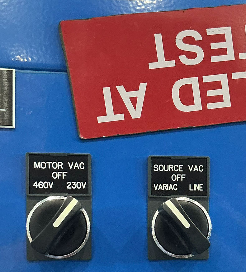
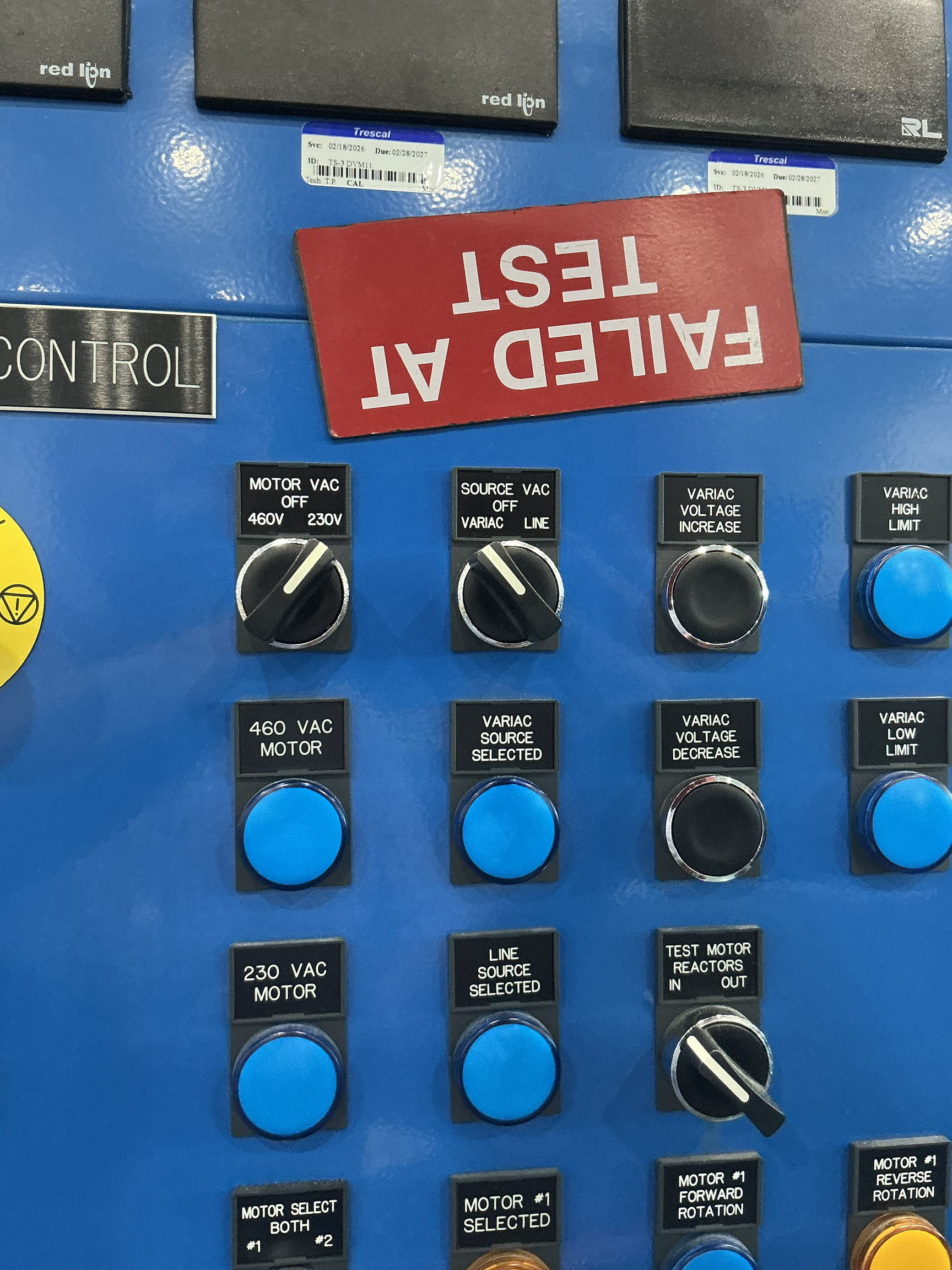
2. Set the Motor VAC to match the voltage of the drive identified in Step 1.
3. Set the "SOURCE VAC" to "VARIAC" for 200 Volt drives and set to "LINE" for 480 Volt Drives. Set to "VARIAC" for 600 Volt Drives at 600 Volt test Stands
4. Place a magnet or indicator to indicate the voltage has been selected. If tester has to leave the station, return voltages to OFF and start over at step 1 upon return
Identified Hazards & Required Controls (Most Critical First)
| Energy / Category | Hazard Description | Risk Level | Mandatory Control Measures |
|---|---|---|---|
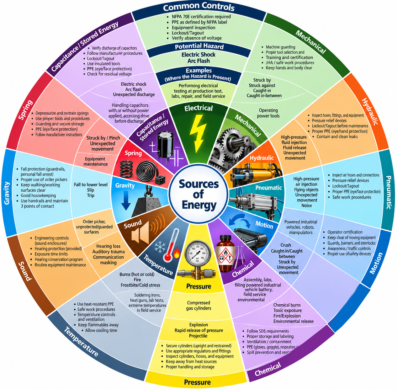
| Electric Shock or Arc Flash | While there is no electrical hazard at this time, failure to correctly select the voltage can cause in arc flash inside the drive at a subsequent step |
Score: 25 Moderate |
1. Multiple step voltage verification by trained, competent associate
2. Drive cover contains the arc blast energy 3. Fast acting short circuit protection |
Verify the critical electromechanical components match the description in the production order
Identified Hazards & Required Controls (Most Critical First)
| Energy / Category | Hazard Description | Risk Level | Mandatory Control Measures |
|---|---|---|---|
| Electric Shock or Arc Flash | No hazard at this step but failure to perform this step can lead to damaged parts at subsequent steps |
Score: 9 Low |
1. Correct components are checked three times: upon pulling for the order, upon installation, and at test
|
1. Verify the critical electromechanical components match the description in the production order
2. For Bypass units, connect communication cable to bypass board to capture serial number
3. Perform continuity check to ensure correct wiring
Identified Hazards & Required Controls (Most Critical First)
| Energy / Category | Hazard Description | Risk Level | Mandatory Control Measures |
|---|---|---|---|
| Electric Shock or Arc Flash | No hazard at this step but failure to perform this step can lead to damaged parts at subsequent steps |
Score: 9 Low |
1. Correct components are checked three times: upon pulling for the order, upon installation, and at test
2. Competent tester performing continuity check reduces the chance of arc flash and quality defects at power-on step |
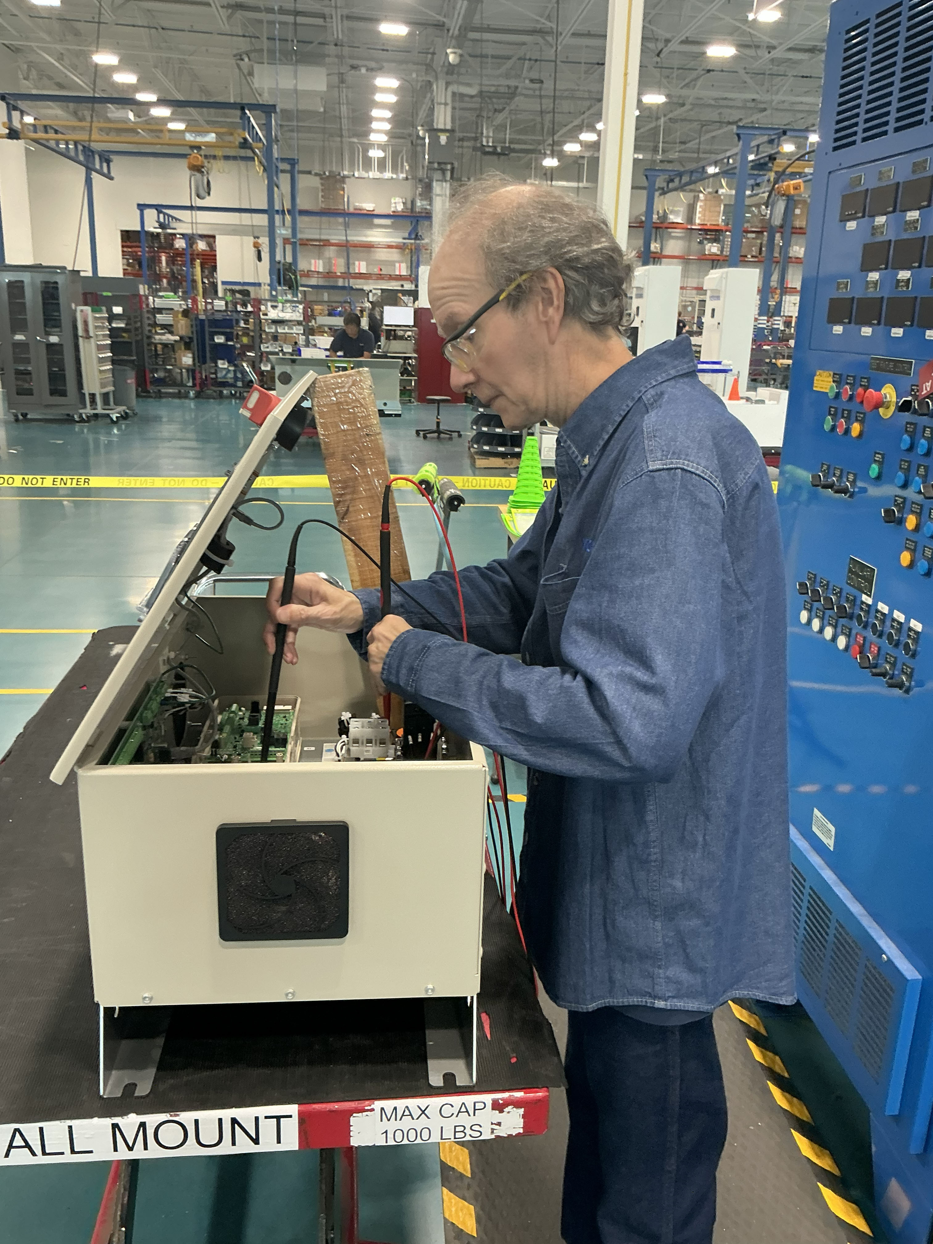
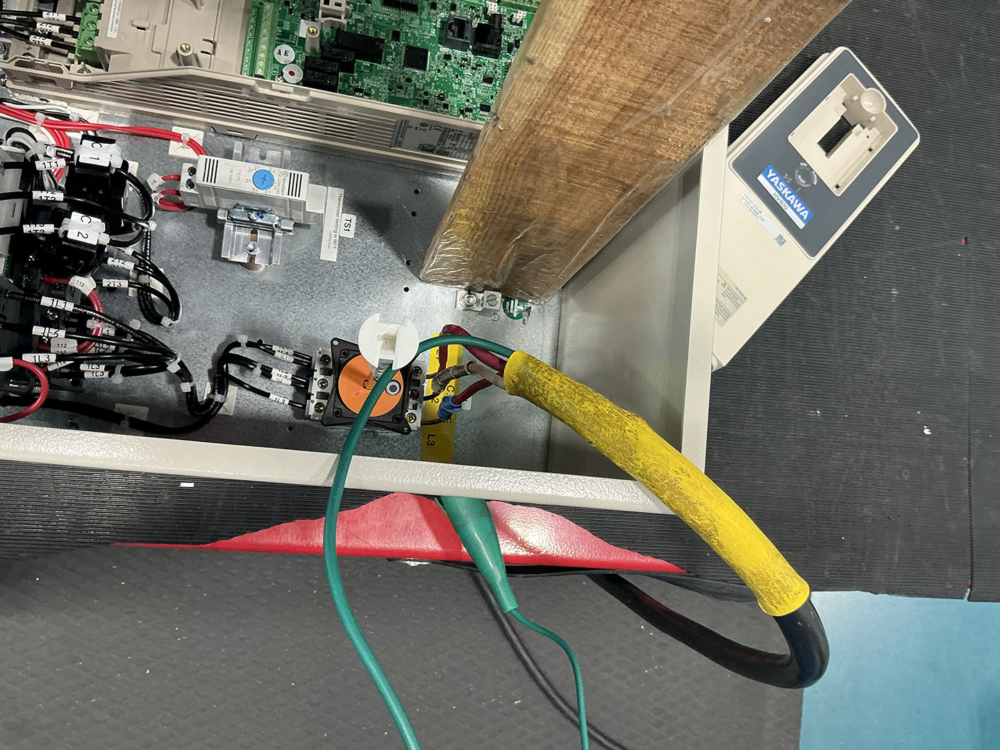
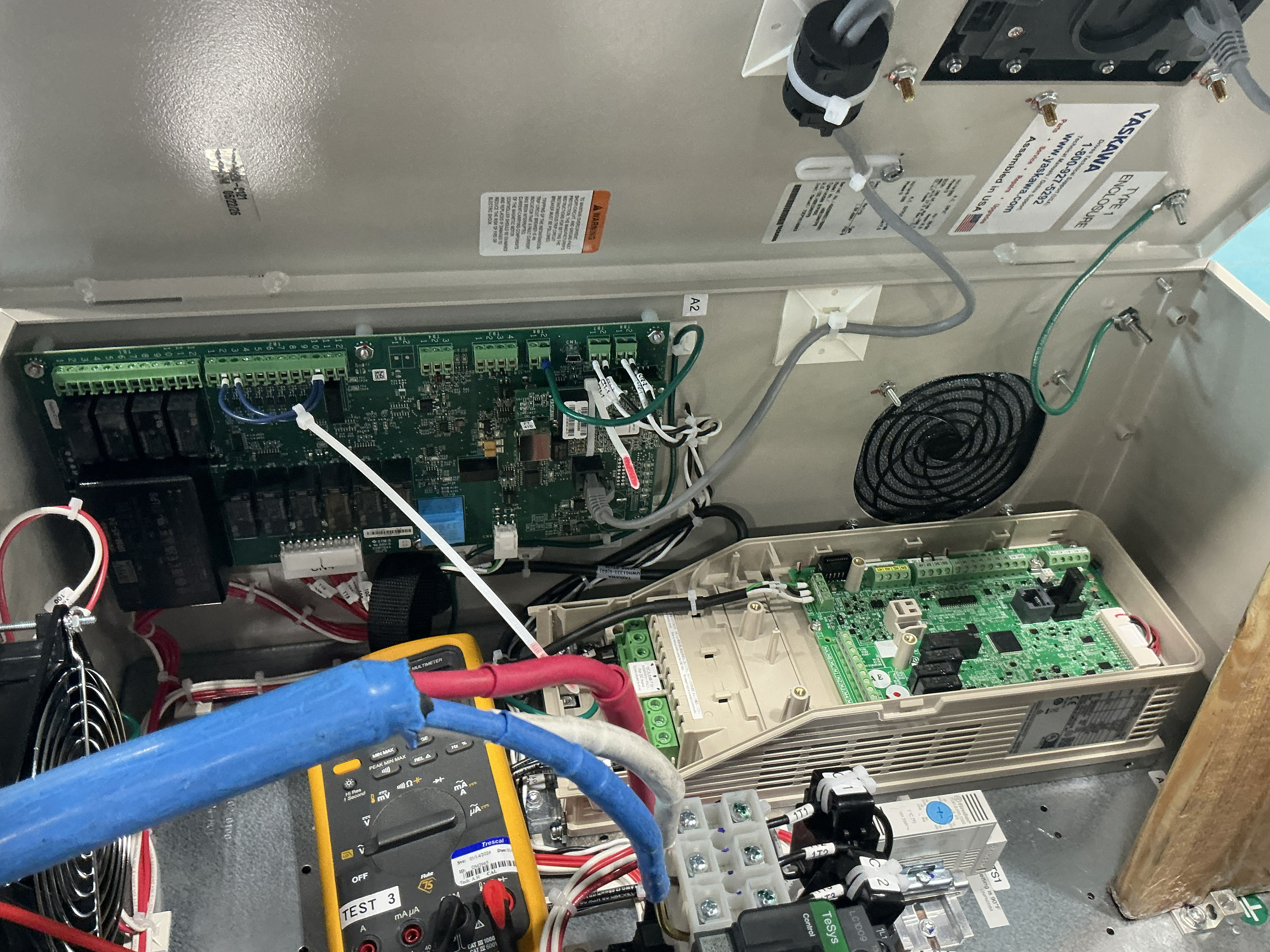
1. Connect AC input cables to UUT input component (e.g., Circuit Breaker, Disconnect, directly to drive on some configured units)
2. Connect motor output wires
3. On Bypass units, install Safety Circuit Jumpers
Identified Hazards & Required Controls (Most Critical First)
| Energy / Category | Hazard Description | Risk Level | Mandatory Control Measures |
|---|---|---|---|
| Electric Shock or Arc Flash | Incorrect installation can cause arc flash hazard at subsequent step |
Score: 30 Moderate |
1. Color coded phase wire leads
2. Installation by trained, competent assocaite |
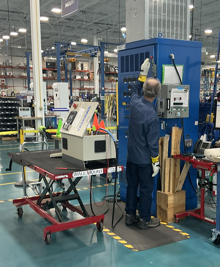
1. Don required PPE (ear plugs required when applying power, electrical gloves with leather protectors, long sleeve all natural fiber shirt - Safety Glasses and Electrical Hazard shoes are required for all steps in this process)
2. Using the Left Hand Rule, turn the Test Stand Disconnect to the On position.
Identified Hazards & Required Controls (Most Critical First)
| Energy / Category | Hazard Description | Risk Level | Mandatory Control Measures |
|---|---|---|---|
| Electric Shock or Arc Flash | Arc flash inside the variable frequency drive if the wrong voltage is applied |
Score: 30 Moderate |
1. All of the previous steps are designed to prevent an arc flash within the variable frequency drive
2. The drive cover is installed and will contain the arc flash and blast 3. The tester is at the test stand and not standing over or directly in front of the drive. This places the person outside of the arc flash boundary. 4. Fast acting short circuit protection immediately removes power to the drive to control the blast |
| Electric Shock or Arc Flash | Arc flash at other components if the test leads are installed incorrectly, there is miswiring or loose power connections in the unit, or incorrect components installed |
Score: 18 Moderate |
1. Administrative controls taken at previous steps, including multiple checks prior to this job, are designed to protect against this failure.
2. The tester is at the test stand and not standing over or directly in front of the drive. This places the person outside of the arc flash boundary. 3. Fast acting short circuit protection immediately removes power to the drive to control the blast |
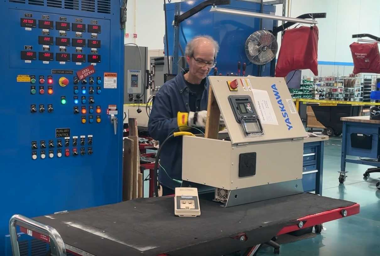
1. Check voltage going into the drive at the disconnect and at the drive input
• If the correct voltage is at the disconnect but incorrect at the drive, check voltages at each component in line to troubleshoot
2. Perform Factory Reset on the Drive
3. Check fan air flow is in the correct direction
4. Set thermostat
5. Connect cable to bypass board (Bypass units only) to perform Load Bank Test
6. Turn Test Stand Disconnect to Off Position
7. Reset Drive and Power Power Switches on test stand to Zero or Off position
Identified Hazards & Required Controls (Most Critical First)
| Energy / Category | Hazard Description | Risk Level | Mandatory Control Measures |
|---|---|---|---|
| Electric Shock or Arc Flash | Electric shock from contact with exposed voltage |
Score: 30 Moderate |
1. Process performed by trained testers who are certified in NFPA 70E requirements
2. Electrical PPE 3. Fast acting short circuit protection reduces potential severity |
Eye Protection
Warning: Undefined array key "EyeSafetyGlassesSideShields" in /homepages/8/d663429354/htdocs/JHA/viewJHA.php on line 385
Warning: Undefined array key "EyeVentedGoggles" in /homepages/8/d663429354/htdocs/JHA/viewJHA.php on line 386
Warning: Undefined array key "EyeNonVentedGoggles" in /homepages/8/d663429354/htdocs/JHA/viewJHA.php on line 387
Warning: Undefined array key "EyeWeldingHelmetShield" in /homepages/8/d663429354/htdocs/JHA/viewJHA.php on line 388
Warning: Undefined array key "EyeFaceShield" in /homepages/8/d663429354/htdocs/JHA/viewJHA.php on line 389
Hearing Protection
Warning: Undefined array key "HearingProtection" in /homepages/8/d663429354/htdocs/JHA/viewJHA.php on line 398
Warning: Undefined array key "HearingAttenuationLevel" in /homepages/8/d663429354/htdocs/JHA/viewJHA.php on line 399
Foot Protection
Warning: Undefined array key "FootToe" in /homepages/8/d663429354/htdocs/JHA/viewJHA.php on line 408
Warning: Undefined array key "FootElectrical" in /homepages/8/d663429354/htdocs/JHA/viewJHA.php on line 409
Warning: Undefined array key "FootESD" in /homepages/8/d663429354/htdocs/JHA/viewJHA.php on line 410
Warning: Undefined array key "FootChemical" in /homepages/8/d663429354/htdocs/JHA/viewJHA.php on line 411
Respiratory
Warning: Undefined array key "RespiratoryFilteredFaceMask" in /homepages/8/d663429354/htdocs/JHA/viewJHA.php on line 420
Warning: Undefined array key "RespiratoryHalfFaceP100" in /homepages/8/d663429354/htdocs/JHA/viewJHA.php on line 421
Warning: Undefined array key "RespiratoryHalfFaceOrganicVapor" in /homepages/8/d663429354/htdocs/JHA/viewJHA.php on line 422
Electrical / Arc Flash
Warning: Undefined array key "ElectricalClass0Gloves" in /homepages/8/d663429354/htdocs/JHA/viewJHA.php on line 431
Warning: Undefined array key "ElectricalClass1Gloves" in /homepages/8/d663429354/htdocs/JHA/viewJHA.php on line 432
Warning: Undefined array key "ElectricalCat1Arc" in /homepages/8/d663429354/htdocs/JHA/viewJHA.php on line 433
Warning: Undefined array key "ElectricalCat2Arc" in /homepages/8/d663429354/htdocs/JHA/viewJHA.php on line 434
Warning: Undefined array key "ElectricalArcRatedClothes" in /homepages/8/d663429354/htdocs/JHA/viewJHA.php on line 435
Environmental Conditions
Post-Secondary Electronics Education
Associate’s degree in electronics preferred, or equivalent related work experience; presently enrolled in associate degree program acceptable.
OJT
Ability to use test procedures
OJT
Solid electrical circuit troubleshooting and repair skills, demonstrated understanding of state-of-the-art components and circuitry such as microprocessors, bus structured circuitry, PWM technology, etc
NFPA 70E Certifiec
NFPA 70E certification required every three years
Control of Hazardous Energy (Lockout/Tagout)
LOTO training required every three years
| Chemical Name | Secondary Container | SDS on File | SDS Sheet |
|---|---|---|---|
| Isopropyl Alcohol | Yes | Yes | View SDS |
| Tool / Equipment | Inspection & Maintenance Protocol |
|---|---|
| Test Stand | 1. Inspect all power cords at beginning of each shift for signs of damage. 2. Drive power lead switch on side of unit turned to off position when not at stand. Disconnect to off when power is not applied. 3. Annual calibration |
| Digital multi-meter | Annual calibration. Verify against known power source prior to using multimeter to verify absence of voltage when used for Lockout/Tagout purposes |
| Hand tools including screwdrivers and wrenches | Verify no damage to insulated handles |